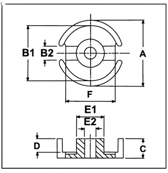
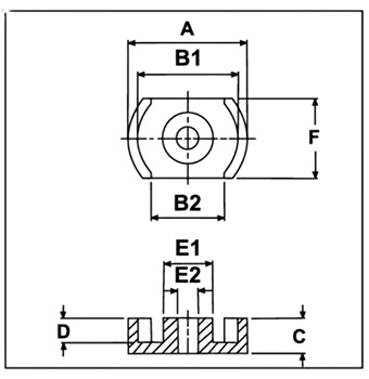
RM Cores: 40% space savings over Pot Cores. But one downside is that they give precise route winding for well separation. Baling silos available in a variety of sizes, including RM6 and RM8 with a closed top cover. Diagram of RM core appropriate for: Common usage include differential inductors. Power inductors Filter coils Telecom Coils Broad band Transformers


| Type | Fig | DIMENSIONS (mm) | Effective Parameters | AL (nH)+30% -20% | |||||||||||||
|---|---|---|---|---|---|---|---|---|---|---|---|---|---|---|---|---|---|
| A | B1 | B2 | C | D | E | F | G | Le(mm) | Ae(mm²) | CF196 | CF139 | CF140 | CF130 | CF195 | CF199 | ||
| RM14 | 10 | 41.6±0.6 | 17.0 min | 29.5±0.5 | 30.2-0.2 | 20.08±0.6 | 14.75±0.25 | 34.3±0.5 | 18.7±0.3 | 70 | 200 | 5200 | 5450 | - | 6900 | 9300 | - |
| RM12 | 10 | 36.75±0.65 | 13.4 min. | 25.5±0.5 | 24.6-0.2 | 16.08±0.6 | 12.6±0.2 | 29.25±0.55 | 16.1±0.3 | 57.3 | 138 | 4800 | 5000 | - | 6500 | 9100 | - |
| RM10 | 10 | 27.85±0.65 | 11.9 min. | 21.65±0.45 | 18.7-0.2 | 12.04±0.6 | 10.7±0.2 | 24.15±0.55 | 13.2±0.3 | 44 | 98 | 4000 | 4200 | - | 5300 | 7100 | - |
| RM8 | 10 | 22.75±0.45 | 9.8 min. | 17.3±0.3 | 16.5-0.2 | 10.08±0.4 | 8.4±0.15 | 19.25±0.45 | 10.8±0.2 | 38 | 64 | 2500 | 2600 | - | 3100 | 3900 | - |
| RM6 | 10 | 17.6±0.35 | 8.4 min | 12.65±0.25 | 12.5-0.2 | 8.0±0.4 | 6.30±0.15 | 14.4±0.3 | 8.0±0.3 | 28.6 | 36.6 | 2000 | 2100 | - | 2600 | 3350 | - |